A walk-through guide to setting up a set of FireBricks as LNSs for an ISP talking to a wholesaler such as BT Wholesale, TalkTalk Business or Zen. You should also read the FB6202 manual which will cover parts of this in more detail.
FireBrick FB6202
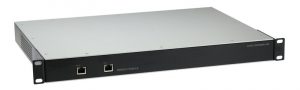
A FireBrick *FB6202 is the LNS model for the FB6000 series, designed specifically for ISP grade service.
- 1U rackmount
- Dual PSU, very low power consumption
- ~1Gbit/s throughput of normal traffic
- Up to 65000 L2TP sessions over 20000 tunnels
- Scaleable solution allowing multiple gigabits of L2TP traffic
FireBrick FB2900
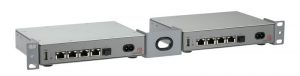
A FireBrick FB2900 is a more general-purpose office firewall solution which can be used as an LNS for smaller installations, or as a starting point before growing into an FB6202 or as a test LNS. You should be aware of the following considerations:
- ~750Mbit/s throughput of normal traffic
- Up to 200 L2TP sessions
- Single PSU
- Can be rack-mounted as one or two units in 1U
*The FB6000 series is due to be replaced in Q1 or Q2 of 2021, by the FB9000 series. A few improvements include a more powerful CPU, more RAM & Ten SFP ports (Two at 10Gbit/s & eight at 1Gbit/s). Please contact us or periodically check our News page for updates on features & availability of the new FB9000 series.
FireBrick as an LNS: Features at a glance
FireBrick can act as L2TP Network Server:
- Accepts L2TP connections from carriers (e.g. BT, TT, etc)
- Can use local config to handle connection or RADIUS
- Can terminate a connection to IPv4 and/or IPv6
- Can relay connection to another LNS
- Can relay using a separate session steering RADIUS
- Handles IPv6 DHCPv6 PD automatically to provide end-users with full native IPv6
- Handles BCP38 source filtering automatically, including 2002::/16 and bonded and fallback line uplinks
- Handles bonding multiple lines automatically
- Fast, efficient PPP negotiation
- Damping of lines to meet aggregate capacity, and ability to share aggregate capacity
L2TP using RADIUS:
- Multiple RADIUS servers
- Load sharing and fall back, separate for auth and acct
- Can use RADIUS for authentication, with standard servers like FREERADIUS
- A free Linux / SQL authentication application is also available free from FireBrick, and we can offer custom RADIUS design to meet your requirements if needed.
- Standard responses for IPv4/IPv6, etc
- Custom responses and attributes for extra features
- Can use RADIUS for accounting
- A free Linux / SQL accounting application is available free from FireBrick
- Standard attributes for accounting
- Custom attributes for metered connections and other features
- Can use RADIUS CoA to force disconnect or change settings
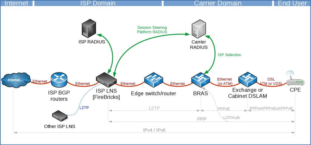
A high-level overview of how it all works
Here is a brief overview of how an end user’s router connects to the internet through you.
- CPE is configured with a valid username and password for your services
- CPE gains ‘sync’ (if DSL) with the local street cabinet (VDSL/G.FAST) or the exchange (ADSL)
- CPE sends username & password over PPP (eg example@myisp)
- The carrier RADIUS selects the ISP based on the realm (the bit after the @)
- The carrier contacts the ISP platform RADIUS servers for where to send the session
- The ISP responds to the platform RADIUS with the IP of the LNS to connect to and the backup LNS (handled by FireBrick)
- The carrier routes the session to the ISPs LNS
- The ISPs FireBrick LNS checks against its own RADIUS for the incoming username
- The ISPs RADIUS responds to its LNS with connection details (IP etc, other options can be given)
- The session is then accepted on to the LNS
- The LNS announces into the ISPs core the IP address(s) by BGP
- The CPE has now connected
Basic config bits
There are lots of small bits of config that you will want to do at some point, these are our of the scope of configuring an LNS, but are things that most FireBricks would want to have configured. These are covered in the manuals.
- Admin users
- NTP servers (Using your own, rather than the defaults)
- SNMP (You can monitor, traffic, CPU, PSU, BGP sessions, L2TP connection counts etc)
- Config backups (eg RANCID, see the manual for examples using curl)
- Syslog targets for logs
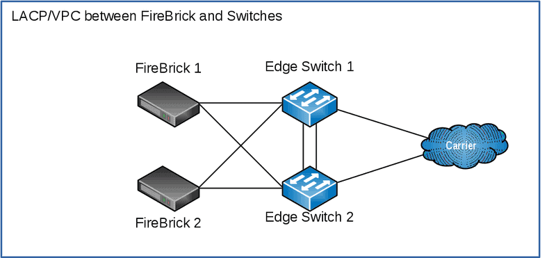
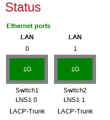
Physical Connections
For this example, we’ll have:
- Two FireBricks (FB2900 or FB6202)
- Two Core or Edge Switches
- Two physical connection to the carrier
Each FireBrick has two interfaces configured as an LACP group, and the switches have a VPC configured.
The carrier treats the interconnects as separate connections, there isn’t LACP here.
You may choose not to have switches between the FireBrick and the carrier and connect the carrier directly to the FireBrick (via a media converter or using the SFP port on the FB2900). However, using a switch is usually more flexible and resilient.
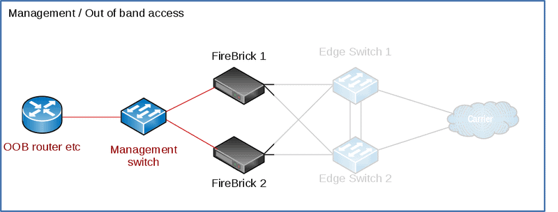
Management / Out of band access
On the FB2900 you can connect a physical interface to your management / out of band network. This can then be used for configuration of the FireBrick, and access to your FireBrick on its public-facing interfaces can be disabled.
We’ll use port 4, and routing table 99 for ‘Management’, your configuration may well be different from this one.
For FB9000 use the serial port on the rear of the unit.
For more details, see the ‘Protecting the FB6000’ section in the manual.
Addressing details for our example
| Carrier Name | Carrier-Y |
| Carrier-Y AS | AS65540 |
| ISP AS | AS65541 |
| Overall prefix on carrier side | 192.0.2.0/24 |
| Carrier-Y interlink #1 VLAN | 1001 |
| Carrier-Y interlink #2 VLAN | 1002 |
| Datacentre LAN VLAN | 101 |
| Carrier-Y internlink Routing Table | 11 |
| Management routing table (OOB) | 99 |
| Carrier-Y interlink #1 /30 | 10.0.0.0/30 |
| Carrier-Y interlink #2 /30 | 10.0.0.4/30 |
| Datacentre LAN subnet | 192.0.2.0/24 2001:DB8::/64 |
| ISP RADIUS Servers IPs | 192.0.2.1 & 192.0.2.2 |
| ISP LNS IPs | 192.0.2.11 & 192.0.2.12 |
| ISP ‘test’ LNS IP | 192.0.2.13 |
| ISP Core Routers | 192.0.2.101 & 192.0.2.102, 2001:DB8::101 & 2001:DB8::102 |
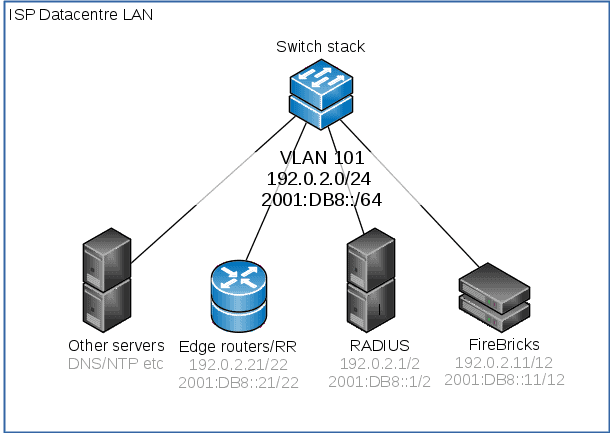
IP connection to datacentre LAN
The datacentre LAN is the network that site the core of the ISP’s other devices – the RADIUS servers, the other BGP route reflectors/routers, DNS, NTP servers and so on. In this example, we’re using a /24 and /64 subnet on VLAN 101. This setup will vary depending on how you have your network configured, but this is the subnet that the FireBricks use to reach your RADIUS servers and core BGP routers.
This is set to use the ‘LAN’ ports as setup above as an LACP bundle of two of the physical ports.
You can omit the default gateway if you are wanting to use BGP for routing.
IP Connection to the carrier
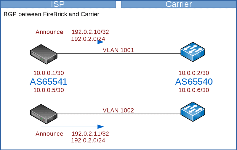
BGP to Carrier
You will announce your LNS and RADIUS addresses to the carrier, typically you’d have a single BGP session per link to the carrier.
Here we will use the FireBrick to handle the BGP – we have two FireBricks and two interconnects to the carrier. You may prefer to run the BGP on a different device or devices according to your needs – eg if you have a larger number of FireBricks than the number of interconnects.
The carrier will announce their IPs to you – these vary between the carrier – eg, BT Wholesale will announce all their BRAS to you – which will be a large number, whilst TalkTalk only announces their a few IPs – which will be their LACs to you.
You will want to configure filters on the BGP connection to limit the prefixes accepted from the carrier or announced to the carrier, but be wary of the carrier increasing the number of prefixes with or without notifying you.
We will configure the interlink interface on a separate routing table. The FB6000 can have separate routing tables which act as completely separate internets.
Using a separate table means you do not have to worry about what prefixes are announced on the BGP link as they will only apply to that routing table.
Whilst we would recommend using a BGP connection like this, if the carrier does not handle BGP then you will need static routes. Using a separate routing table can make this much simpler as you can set a default route to the carrier gateway on the interlink subnet.
When using a separate routing table, you have to take care to correctly configure the routing table on the interface, BGP, RADIUS, L2TP and loopback configuration elements.
Platform RADIUS
- Carriers often provide a pre-connection RADIUS
- The response can reject connection (bad idea) or steer to LNS
- FireBrick has built-in session steering RADIUS server
- Load sharing to multiple LNS – using hashes to group lines
- Fallback responses
- Custom checking allowing special cases, test/debug, etc
- Relay copy of RADIUS to a local server for logging, etc
- Extra custom settings for BT 20CN steering RADIUS
We recommend using RADIUS session steering with the carrier if they support it. Session steering means that the carrier sends a RADIUS request to the ISP before connecting each session by L2TP. The reply steers the connection to a specific LNS.
The connection details include the target (IP address) which will be one of the FireBrick’s address and a pre-agreed hostname which identifies the tunnel level connection, along with a secret to authentication the connection.
The carrier will typically expect you to have two RADIUS endpoints to which they can send requests. One for master and one for backup. Whilst the FB6000 will answer RADIUS on any of its IP addresses, we know some carriers have issues using the interlink IP addresses. We recommend you create two additional loopback addresses for session steering RADIUS.
These addresses are configured as a BGP announced loopback address. You can use MEDs to steer which IP is on which LNSs. If you have more than two LNSs you can ensure that the same IPs are announced from more than one LNS, and let BGP decide which LNS gets the RADIUS requests. RADIUS is a simple question and answer protocol so it does not matter which LNS gets the request.
You can get all your firebricks to answer for both of these addresses. Add these as loopback addresses in the FireBrick config.
The session steering configuration (Platform RADIUS) is very flexible. We suggest you use the same configuration on each LNS so that the replies are consistent regardless of where the request goes. The reply says where to connect the session (as well as hostname and password to use). The reply can be a single LNS or can be more than one reply with a priority tagging if the carrier supports this.
The FB6000 can pick an LNS randomly from a set, or pick one based on a hash of the username, part of the username, or circuit ID. This can be useful when multiple lines are in a bonded arrangement where using the same prefix on a username ensures all of the connections are steered to the same LNS for bonding.
Session steering also allows specific configurations to be based on username, and circuit and so on, so allowing different responses for different carriers and different end-users to be customised if necessary. It is also possible to send a copy of the session steering RADIUS to your own RADIUS server for logging.
L2TP endpoints
The FB6000 will accept L2TP connections on any of its IP addresses, but again we recommend allocating a loopback address or using the address from the LAN rather than the interlink address as we know some carriers cannot handle that.
Unlike RADIUS where any request can go to any LNS, the L2TP connections have a state, and so you will want the address to stay with the particular LNS. Do not have a loopback that floats between LNSs via BGP as this would mean existing connections trying to talk to another LNS.
It is better for the failure to cause a clean timeout on the failed LNS and reconnect (via RADIUS session steering) than to have active sessions traffic go to a different LNS where the session IDs could match and existing session (unlikely, but possible).
The L2TP connection is matched to an incoming L2TP configuration. The RADIUS session steering can be used to specify the hostname and password that is sent so that the correct incoming configuration can be matched.
This can then select specific RADIUS servers to use at the ISP for authorising the connection (though typically a single set of RADIUS servers is used for all connections). It can also specify defaults for DNS, PPP endpoint addresses and so on.
ISP RADIUS
It checks these in order. Each RADIUS configuration can have multiple servers.
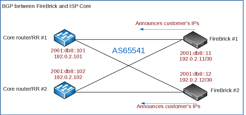
BGP to your core
The FireBrick will want to announce its customers IPs assigned by RADIUS back into your core network to allow routing. (OSPF could be used, but in practice, due to the potentially high number of /32s, it’s not really used)
This can also be used to populate the FireBricks routing table if you’re not using a default route.
RADIUS Accounting and Control messages
RADIUS can also be used for accounting. This involves a RADIUS message at the start and end of each connection, and also interim accounting updates.
Interim accounting is done on a snapshot basis. Normally this is hourly. On the hour, within a second, the details are recorded and then sent by RADIUS. The RADIUS updates may take many minutes to be sent and confirmed by a RADIUS server, but the timestamp on the messages is the hourly snapshot. This is useful where an ISP is charging differently at different times of the day.
Interim updates can also be sent based on reaching a pre-set time or data usage level defines in the authentication RADIUS response.
The FireBrick also supports RADIUS control messages. These can be used to disconnect a connection or to update the details of the connection including line speed, time or data limits, and routing (apart from the PPP endpoint and DNS). (more in manual)
We also have RADIUS to SQL tools on GitHub: https://github.com/revk/FireBrick-RADIUS
Relayed L2TP
- Can relay to secondary LNS – e.g. wholesale DSL, test LNS, etc
- Passes authentication negotiation without re-challenging
- Handles multiple relayed connections (20,000 L2TP tunnels on FB6000)
- Provides additional graph/shaping options on relayed connection
- No LCP echo graphs on relayed connections (yet)
- Does do throughput and up/down state on graphs
- Simple set up using RADIUS response
Other notes
Bonding
As an LNS, the FireBrick will bond traffic at an IP level towards the CPE. As long as the CPE is terminated on the same FireBrick and RADIUS has assigned the same WAN IP and/or IP Block to the circuit, then traffic will be balanced between the two.
Rejecting Connections
You don’t really want to reject a connection – as the CPE will retry every second. You want to accept and dump it into a separate routing table / VRF
CQM Graphs
The FireBrick has Constant Quality Monitoring. When used with the FireBrick acting as an LNS the CQM graphs play an important role.
Per connection monitoring. Each connection is assigned a CQM graph name. This is normally set based on the circuit ID passed by the carrier, or if not present, the username used. A long graph name (over 20 characters) is reduced to a hash.
The name can also be set by RADIUS response (Chargeable User Identity attribute). Each graph shows the send and receive throughput for every 100 seconds. The graph also shows the loss and latency with minimum, average, and maximum per 100 seconds. This is based on an LCP echo sent every second on every connection. The interval can be configured to be lower if you wish (either in the config or by RADIUS).
More details in the manual.
Test LNS platform
If you like, you can have an extra FireBrick (eg an FB2900) as a ‘test’ LNS. You can direct customers, based on a special login, to a this separate LNS for diagnostics, testing, debugging, firewalling, pcapping and so on.
One way to do this is to prefix the CPE’s PPP login with test- and a special ‘match’ config in the RADIUS configuration, and sent the connection to the test LNS (192.0.2.13 in our example)
<match name=”Carrier-Y test” ip=”90.155.53.27-28″ username=”test-*” target-ip=”192.0.2.13″ backup-ip=”192.0.2.11 192.0.2.12″ target-secret=”secret” target-hostname=”Carrier-Y” comment=”Test LNS, captures login eg: test-user@myisp”/>
VoIP and QoS
By default, FireBrick will give priority to small packets – those less than 1000 bytes.
DoS detection and dropping of PPP links
FireBrick can drop PPP sessions and BGP announce blackhole prefixes into your network when a DoS is detected.
IP over LCP
A non-standard coding of PPP packets for IPv4 and IPv6. Rarely used, but useful in some diagnostics as it can bypass IP specific shaping or DPI within the carrier.
More information in the manual
Closed User Group
Each session can have a CUG defined which can be used to restrict the session to a particular port or VLAN on the FireBrick.
More information in the manual
Balancing traffic
FROM the carrier
You need to think about how these are to be load balanced.
The carrier may do ECMP to spread the load
You may be able to announce /32s over each link. (you’d also announce the overall block, eg the /24)
TO the carrier
Traffic being sent from the FireBrick TO the carrier needs some thought – if you have multiple links to the carrier you will want to balance the outbound traffic, typically traffic to your end-users is would be the bulk of the traffic. This can be ECMP / LACP – but LACP can’t be done on
MAC addresses -as there will be very few.
Some carriers – eg BT will have many BRASs their side, so traffic is easier to spread out by LACP. Other carriers, eg TT only have a couple of
IPs.
The answer is to use a public /24 – this could overlap with real IPs if needed as they will only be used on the carrier interlink. but best to keep them separate to the IPs allocated to your end-users.
You can then add multiple IP addresses to each LNS and announce them to the carrier.